Category Archives: Studio Build Log

Step 8: Cupboards

I wanted fitted cupboards for all my tools, audio toys and air circulation equipment.

Measure the space and make a design

cupboards3bThe talented will spot that there is a problem with my design. Sensible cupboards have a back on them to give them lateral support. Learn from my mistake, add some sheets of whatever is cheap to the back. MDF, OSB, Ply, anything.

From my design I measured all the sheets I needed and took the designs to my local builders merchant. They have an F-off-big saw to make this stuff all nice and square. Do not cut sheets of MDF by hand, it gives off nasty dust and is a massive ball-ache.

Got Wood?

So, I managed to get it all in the car and get it home. TravisPerkins did all the hard work sawing it up. 20p a cut, oh my god that is worth it.

Next up, I started assembling my design and quickly realised my mistake. Without a back plane there was nothing to stabilise the whole thing. By the time I’d realised the merchant was shut, for some reason I lost it and put corner braces in. To this day, I’m not sure why.

By the time I’d finished it looked like this:
IMG_20140201_152131
The vertical struts are for the doors to close against. The corner braces are because I am new to this.

The rest of this went well, I was particularly proud of the drill stencil I made for the hinges.IMG_20140209_094106

Step 7: Floor covering

So, in this episode, our intrepid studio builder wants to cover his floor in something comfy.

Considerations including:

  • Having made a wonderful wooden drum out of his floor we now need to deaden it.
  • Having a low ceiling there’s a chance the room will make a nice comb filter floor to ceiling, so I need to deaden that too.

The logical choice therefore was carpet to stop reflections in the room with a sound stopping underlay to deaden the floor itself acting as a drum.

I chose to use a commercial grade rubber backed carpet (like you get in shops) on top of a product intended as a wood / laminate underlay, and I’m bloody glad I did.

To be precise, the underlay was part code A300 from customaudiodesigns.co.uk

The combination has worked a charm, there’s virtually no resonance from the wooden floor at all.

So what about the process of putting it down.

Step one was rolling out the underlay:

2013-12-08 14.52.46
Arriba Arriba…
underlay, underlay
…Underlay, Underlay


MAKE SURE you sweep up thoroughly before you start this, bits of grit can perforate the foil. This is more of an issue for laminate floor which doesn’t like damp coming up from below.

As you can see, I rolled the 2 intact stripes, foil side down along each side and then did the mucking about with the bits that needed cutting in the middle. The idea was to lap up the walls and hide this seam behind the skirting.

I used spray carpet adhesive to glue the foil to the floor and stop it moving. Once I’d cut the middle strips of underlay to size and laid them out I then used foil tape to attach it all together. This also worked well and was easy enough to do.

I was pretty damn chuffed with the finish of this layer, so proud in fact that I totally neglected to take a photo. What a twat.

What I also lack photos of are the next steps, putting carpet down is fairly clear, it came in a roll, I rolled it out and used more spray adhesive to fix it to the underlay. I paid special attention to where my office chair was going to go as the wheels on those tend to ruck carpet up.

EDIT: About a year on the carpet is now rucking up under the office chair even after I used a metric s**t-load of glue. I’m wondering whether it’s pulled the underlay up and is causing both to ripple, but without taking my nice floor apart I’ll never know.


Step 6: Paint all the things and second fix

Not much to comment on here other than it’s better to paint the walls and ceiling before putting the final floor covering down. Common sense really.

I painted the walls and ceiling with the same very slightly off white colour.

Here be pictures of painted walls.

2013-11-28 17.32.55 2013-11-28 17.33.02 2013-11-28 17.33.14 2013-11-28 17.33.29 2013-11-28 17.33.46


Second fix electrics went without  a hitch. At the last minute I added a separate, dedicated earth wire from each of the clean ring sockets back to the board. I did this in a vague attempt to minimise earth loops. My understanding is that this is close to a star earth, although I’d welcome comment from someone who knows more about this. I hid it under the plasterboard and stuck it down where it ran across the base of the door way.

Once we were done I wanted to know what the resistance was on the earth. The maximum acceptable for Building regs is 50Ohms. I asked a tame sparky with the right gadget to come and check my wiring and earth ratings. Turns out I had achieved 4.85 Ohms. Job well done.

2013-12-02 19.19.242013-12-07 14.55.40

Step 5: Plasterboard and sweet pink plastery goodness

Not much to report here. After the last post I also added res bar to the ceiling.

The biggest concern going is DO NOT SCREW THROUGH THE PLASTERBOARD INTO THE BATTENS. If you do, you will add an acoustic brige and that res bar is suddenly useless (not to mention expensive and complicated).

To expand: If the screw touches both wood and plasterboard, they become one joined acoustic surface and any vibration in the wall is now transmitted straight into the room.

The only thing I did which was a tad unusual is use Silicone to seal the plasterboard layers to each other. I seem to have gotten away with this but it could have been a big mistake as I really had no idea whether the acetic acid that stuff gives off when curing would mess up the plaster. As it was, I got away with it, although it seems to have had a slightly iffy reaction with the acoustic membrane.

Basically, I should have used something like decorators caulking.

IMG_20131101_151309 IMG_20131101_151244


I got a professional to do the plastering.

I group plastering with golf:

  • You have to do the same, ostensibly boring, thing over and over again.
  • Just one cock up can massively ruin your whole session.
  • Other people are good at it and, perversely, some of them even seem to enjoy it.

Without further ado, I give you…. pink walls:

IMG_20131112_170848IMG_20131112_170809 IMG_20131112_170829 IMG_20131112_170841

Step 4: First fix wiring and preparing for the plasterboard

Wiring and Earth

I wired my studio to allow for 2 ring mains and some lighting and fans.

All the wires lead back to the corner of the room where the SWA (armoured) cable and the cat5e comes in from the house.

The lighting, fans and one ring used the earth that came from the house. The other Ring (aka: the clean ring) uses a bunch of earth rods and a load of left over concrete reinforcement mesh which I buried around the back of studio. The thinking is that wet soil provides a better earth, so this is all buried near the gutter downpipe. I will pair the guttering up with a load of water buts and a slowly dripping tap to try and keep it at an optimum condition.

Wall preparation, sealing the floor and adding the resilient bar

I wanted 3 walls of the studio covered with plaster, the 4th and final wall has cupboards covering it from floor to ceiling so it doesn’t matter so much how it looks.

In order to achieve the best possible sound isolation, I used a product called resilient bar (aka: resilient channel) to isolate the plasterboard from the walls. Resilient bar is a 2 part long thin sheet of metal which presents two flanges one onto which the plasterboard screws and one that screws to the wall. I recommend you look up how this product works if you’ve never heard of it.

First, I used more of the acoustic membrane (this time the adhesive backed kind) to seal off sound coming from under the floor:

2013-06-08 15.04.17 2013-06-12 20.03.40

You can see how this also serves to cover where the wires come up from under the floor. “D2” in the picture is a note that I want 2 sockets there and that this is on the dirty earth ring.

I then battened out the wall, to match the thickness of the membrane I added small additional stripes of membrane and attached the batten to this. In the following photo you can see the strips of membrane with battens resting nearby (wall ahead). You can also see a finished wall on the right ready for the plasterboard.

2013-06-15 16.57.26

The resilient bar works by minimising the contact between the plasterboard and the wall. Depending on the type it should also have holes cut along the angled portion so that the plasterboard flange is only held to the wall flange by a series of small metal bridges. The bar is mounted at 90 degrees to the battens to minimise contact. Compression fitting dense fibreglass between the battens to damp down any sound transmission within that cavity.

My son was a genuine help through this phase handing me screws and running off with my drill or screw bit when it wasn’t in the combi drill. The second photo here shows where the fans go including the one that pulls nice cool air from under the floor. The top one will blow air out through a hole in the wall. These will both be mounted to a heat exchange and built into the cupboards to draw air in from the top of the cupboards and blow it out underneath.

2013-06-22 13.32.12 2013-06-22 13.34.07

Step 3: Walls and Roof

Buildings are created in layers (just like onions, trolls and parfait – whatever the hell that is).

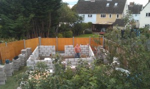
The first layer you make is the frame that holds the rest of the building up. I went for ‘Standard construction’ which means that the structure is effectively a big ‘ole pile of concrete bricks.

Walls

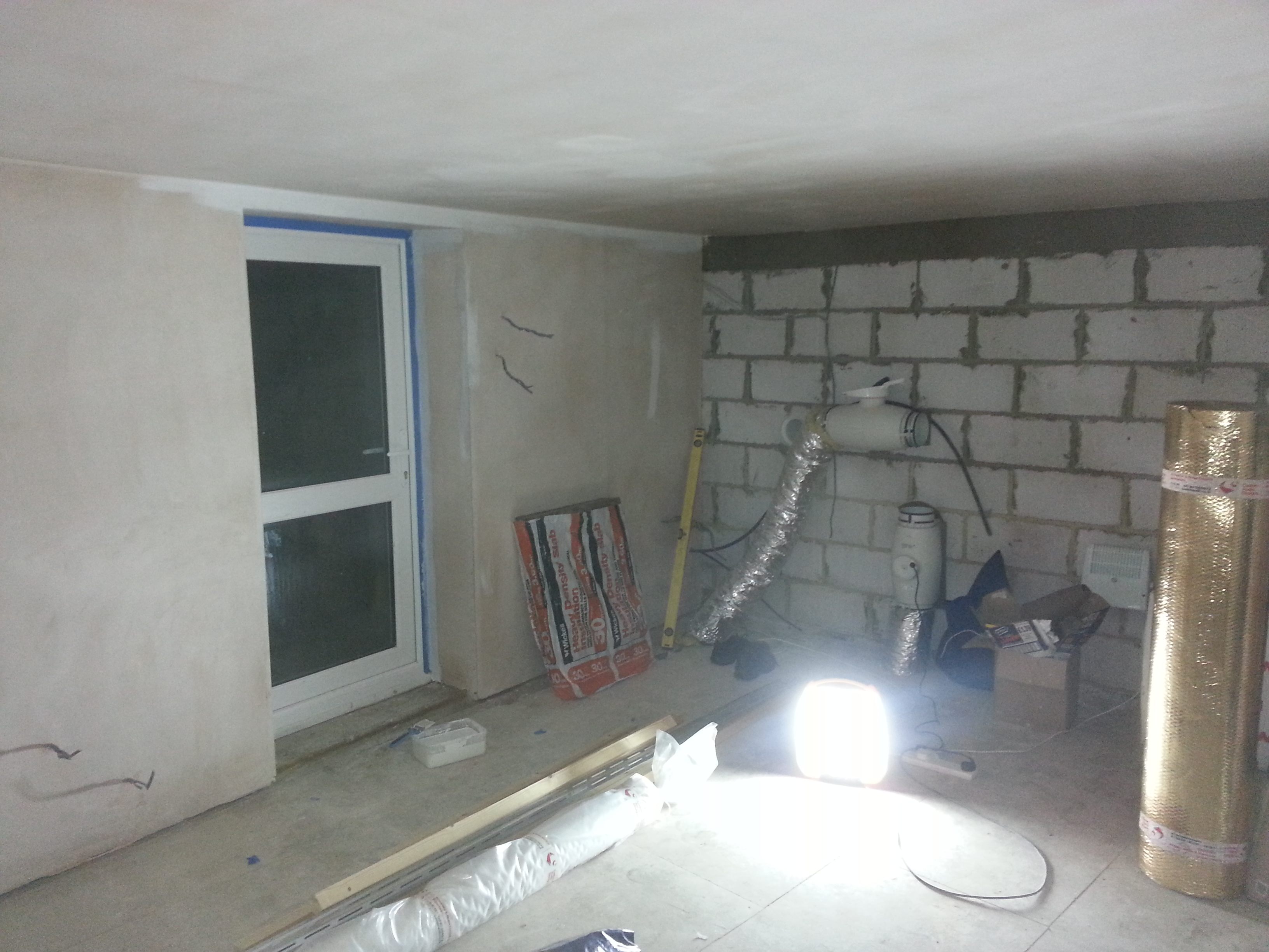
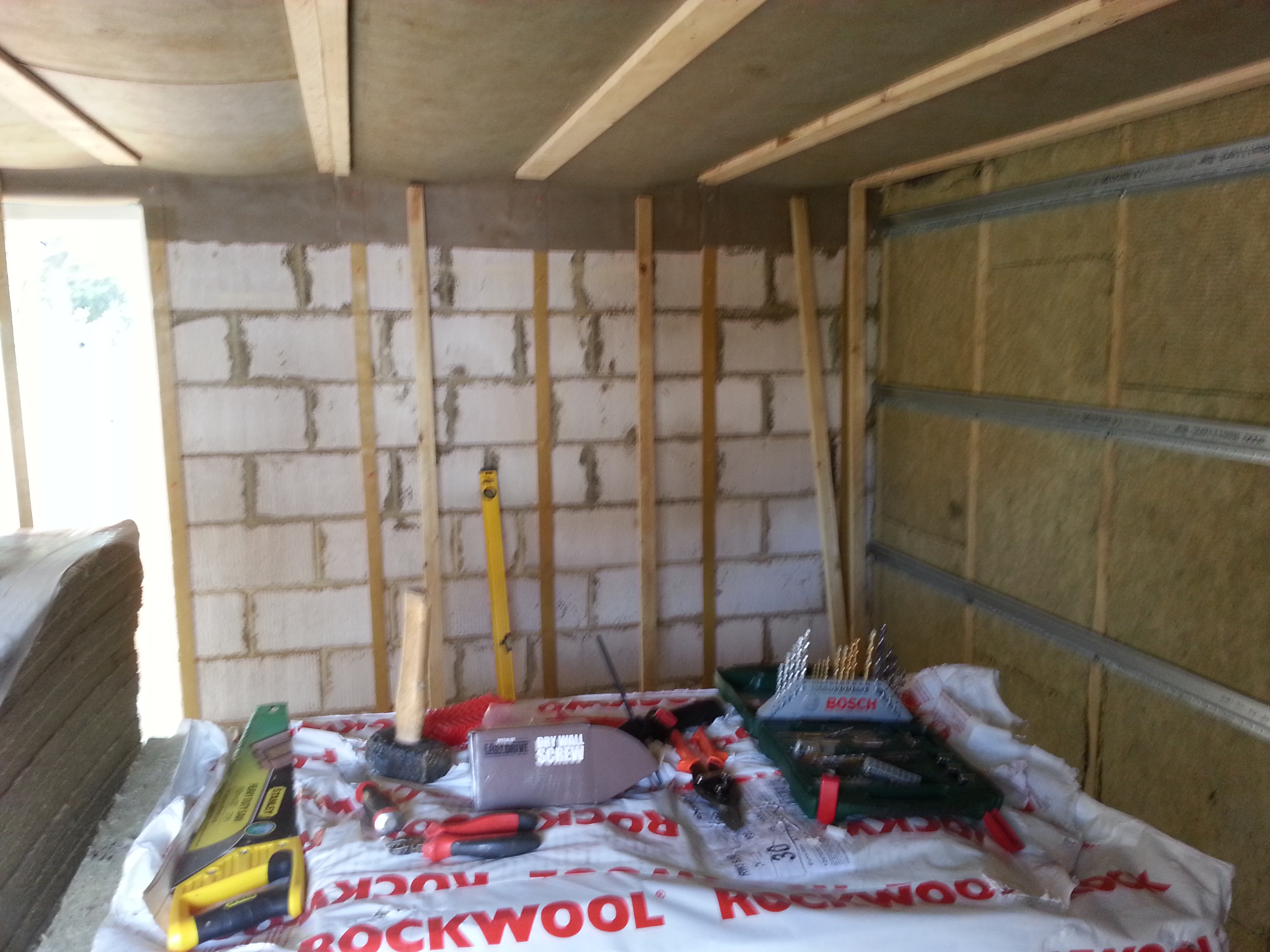
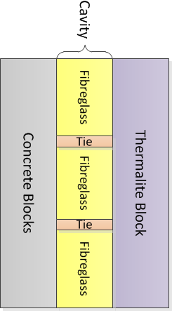
The structural walls for the build are ‘standard construction’ which, in the UK at least, means an inner layer of Thermalite block an air gap aka: ‘cavity’ which contains fibreglass ‘bats’ and an outer layer of Concrete blocks.

To summarise, the walls at this point of progress have this make-up:

OuterWall

I’m not sure if Thermalite is the used lingo outside of the UK. The font of all hearsay refers to them as Autoclaved Aerated Concrete – Snappy. They are effectively light weight bricks with a low thermal conductivity.

Fibreglass bats are basically flimsy sheets of fibreglass quilt that have a constant width (typically ~ 70mm to suit the cavity size) and squared edges to allow the builder to tessellate them when inserting between the two block layers. The other height and length dimensions of the bats are chosen to allow wall ties (stiff metal wires that sit in the mortar at each end and connect the 2 block layers) to be placed at regular intervals. The wall ties tie the Thermalite blocks with the Concrete blocks to keep them the cavity distance constant.

Concrete blocks are as simple as they sound (and bastard heavy).

The principle advantages of this form of construction are:

  • Obvious structural integrity.
  • Thermal Insulation – both the thermalite block and the fibreglass are good insulators.
  • Copes well with rain and damp, the cavity allows any wet to run down the inside of the concrete block without getting to the Thermalite block. The presence of the fibreglass batts doesn’t interfere with this too much.

This form of construction has fairly little acoustic benefit beyond being a large mass.

You can get Acoustic wall ties. Adding these would reduce the transmission of noise through the studio walls. They would not have any effect on the acoustic treatment of the internal studio space. I didn’t use these ties, so I can’t comment on the cost or ease of installation.
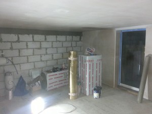
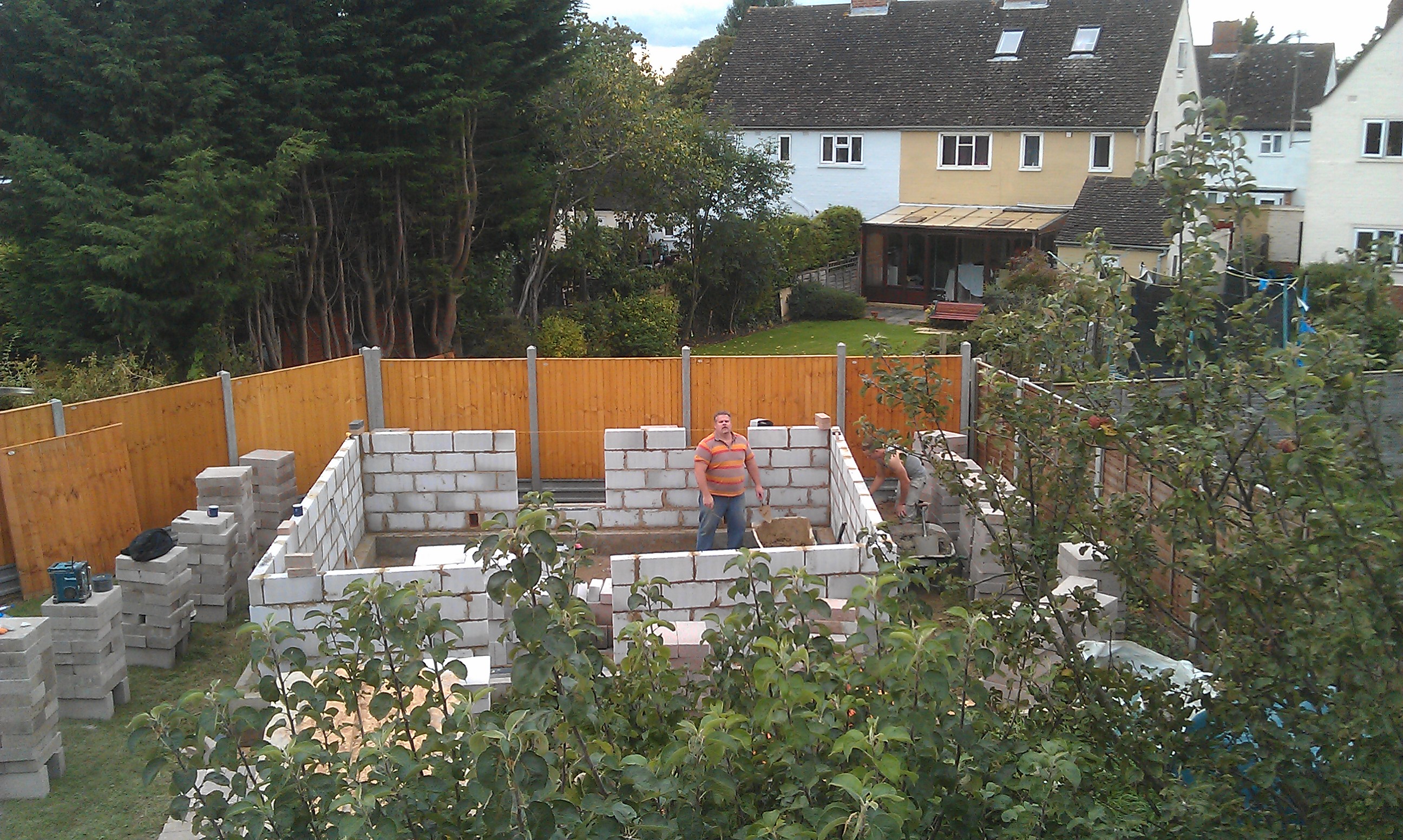
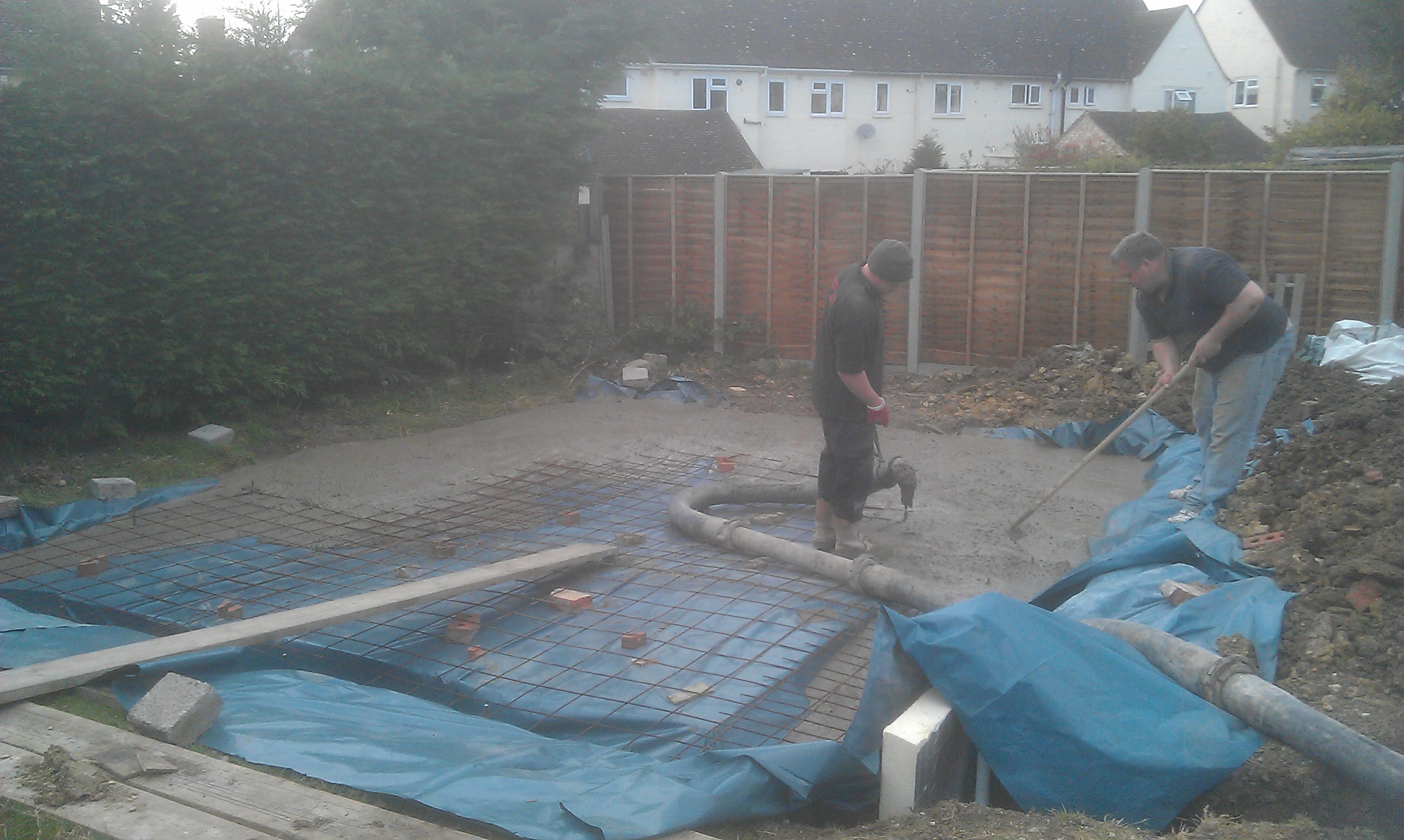
 Action shots

In the first photo we’ve only started work on the outer skin of Concrete Blocks.

2012-09-28 16.34.57

Roof

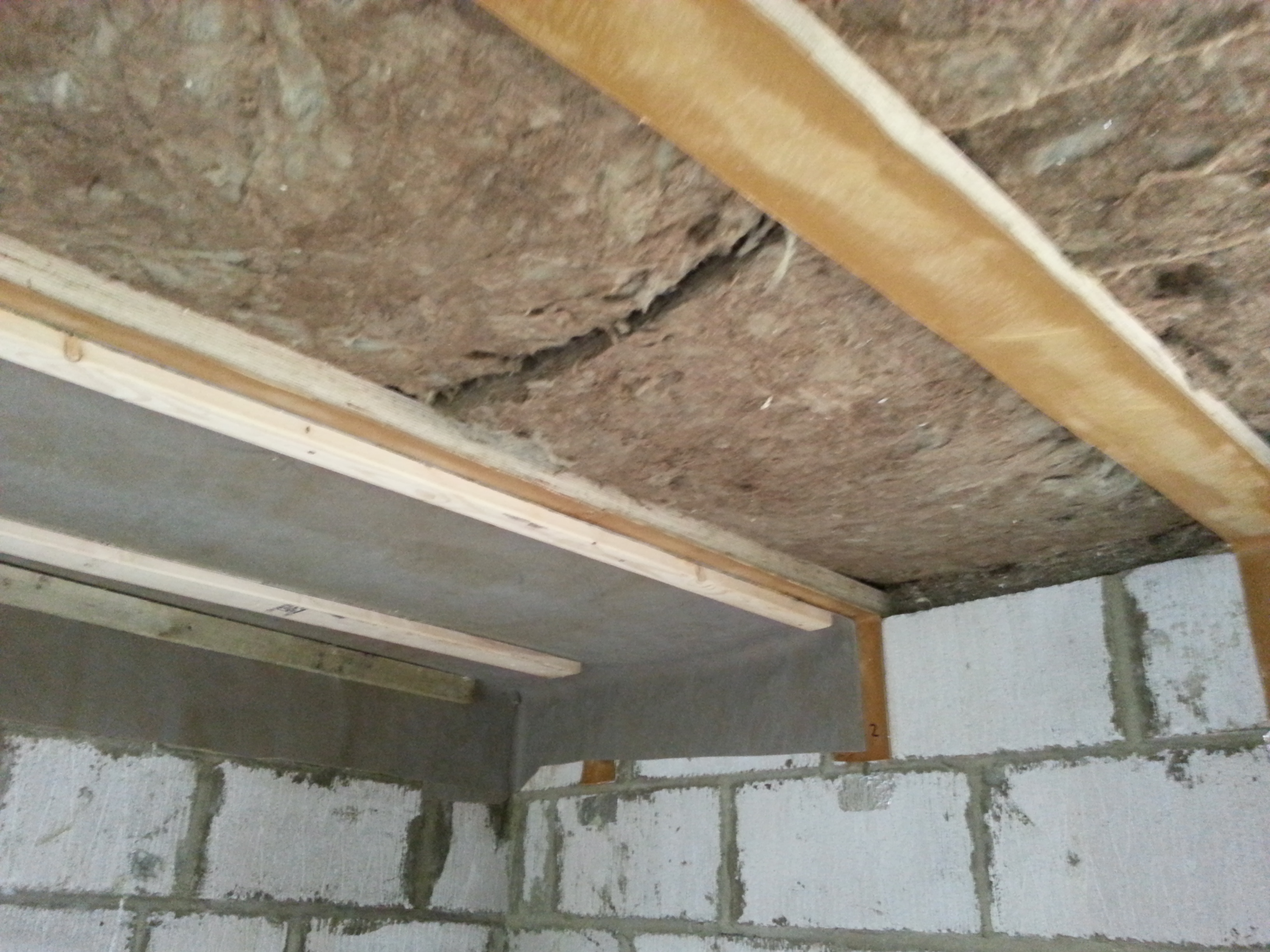
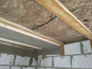
The Roof, as mentioned before is a fibreglass, flat roof construction. There are at least 2 ways of making a flat roof: Closed and Open.

Closed roof design places the insulation above the rafters, but under the final roof deck. The roof insulation is therefore closed off to the room and the humidity that will come from the room will be stopped below the insulation (where it wont condense because it is still warm).

Open roof design places the insulation between the rafters. This typically means that the insulation is open to humidity coming up from the room. It also means that the humidity will come into contact with the cold final surface of the roof. This needs to be mitigated by ventilation to stop it dripping back onto the top of the ceiling.

Open flat roof designs are definitely inferior from a thermal insulation perspective as the rafters bridge the insulation. Their only saving grace is that they are not as tall.

Due to the permitted development laws that I’m using instead of having to apply for planning permission I am constrained on the total height for the build. This is a bit of a pain as a bigger volume of the studio would help with the quality of the sound within.  In order to retain as much usable space as possible, I have opted for the basic open roof design. To be frank, a closed roof design would have meant that my studio was only suitable for children and little folk as I can easily jump and hit my head on the plaster now.

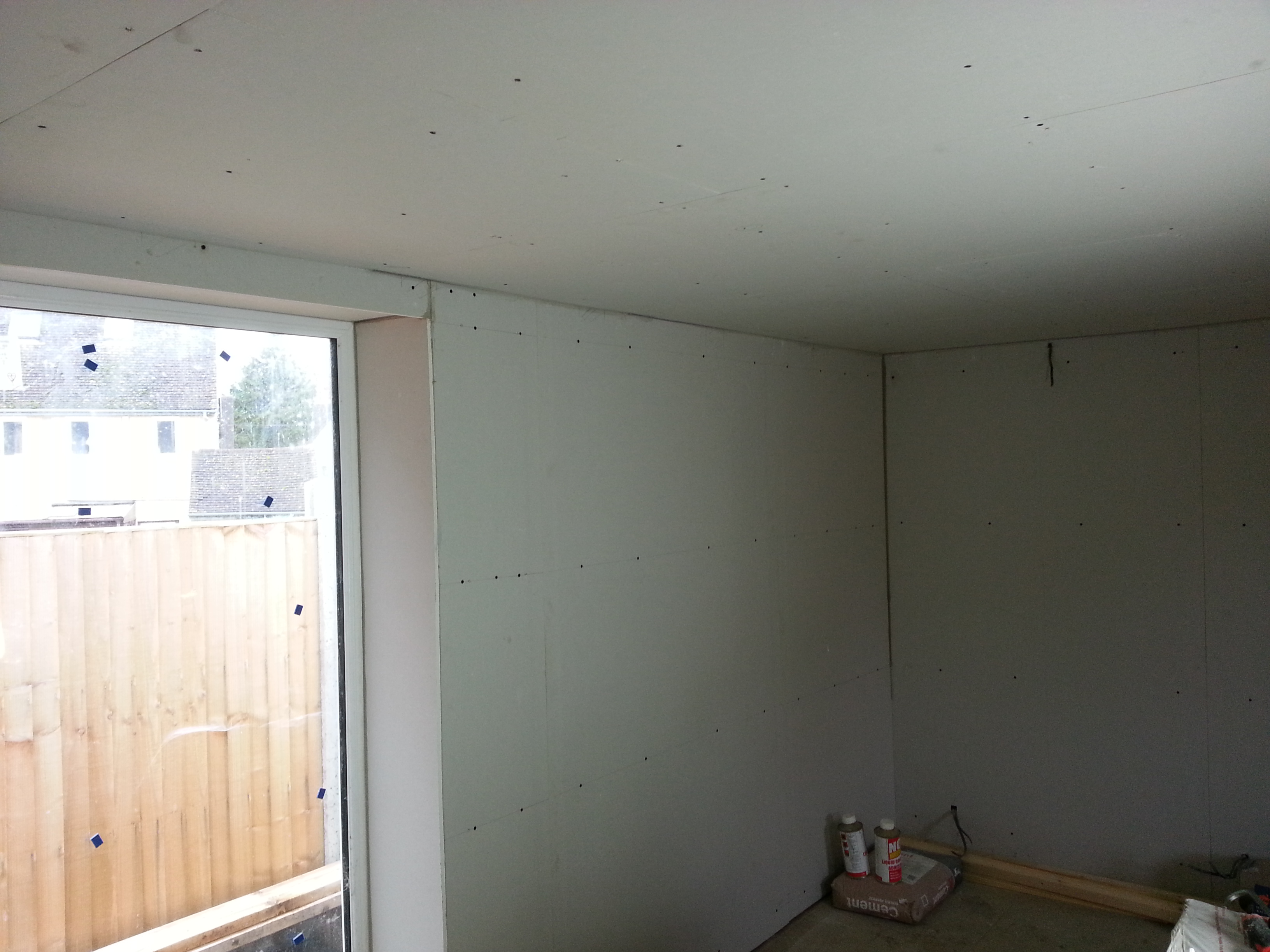
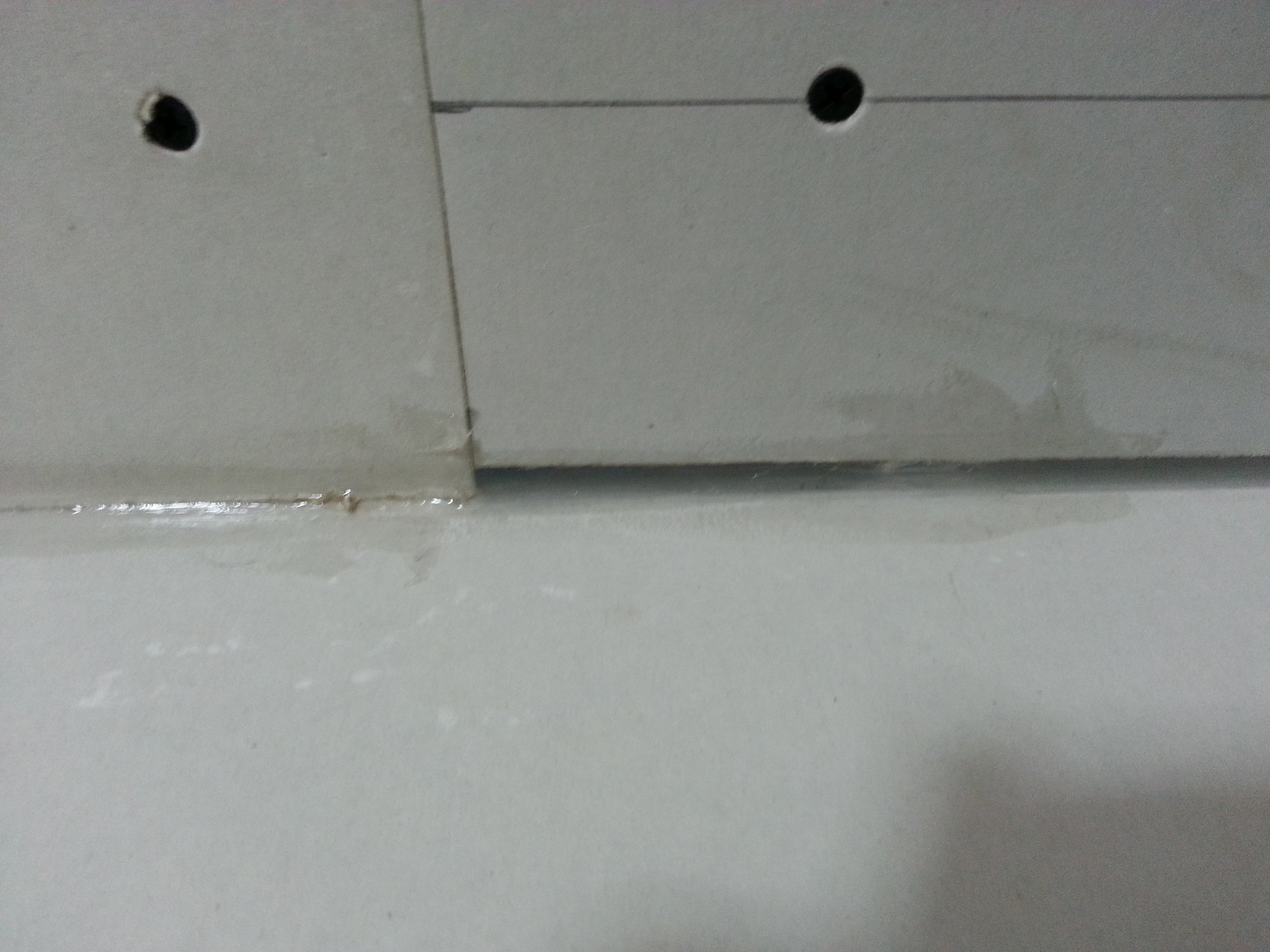
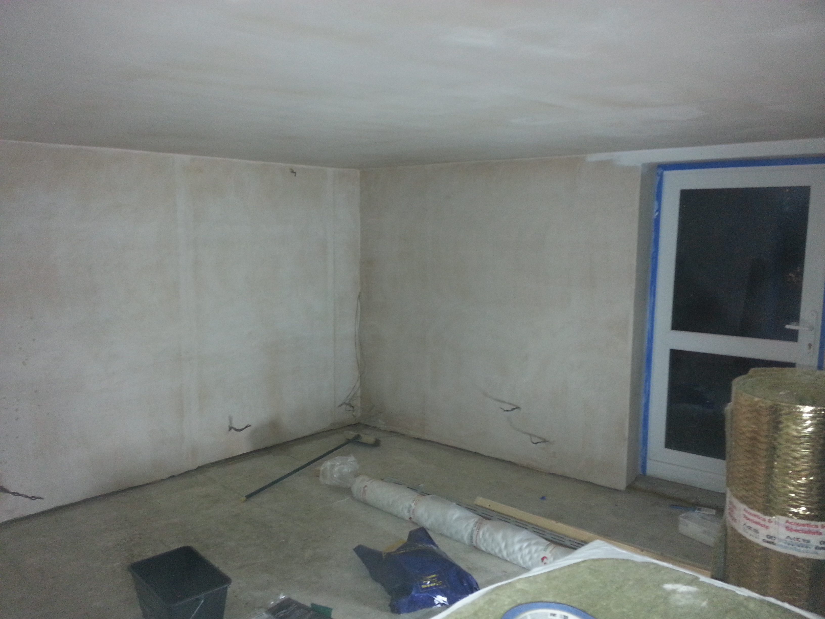
I have however tried to mitigate the acoustic and structural shortcomings of this design. In order to do this I have placed a membrane of high density acoustic membrane BELOW the rafters. As well as stopping the transmission of sound this is a vapour membrane which means that the moisture no longer contacts the cold inside top surface of the roof.

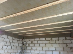
To summarise, the roof structure looks like this (click to embiggen)

OuterRoof

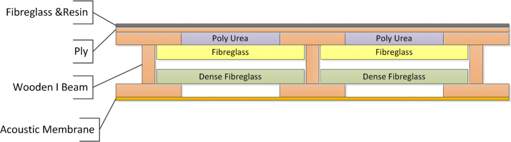
The scale there is way out – The I Beams are 100 mm wide and have a gap of 500 mm between them (i.e. 600 mm centres) but it shows how all the bits fit together.

Another thing that is not shown is that between the I beams and the ply roof deck are items called ‘Tapers’ these are wood and  run along the length of the I Beams in such a way to ensure the deck slants so water runs off.

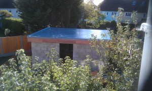
The view from the outside:

2012-10-16 15.20.02

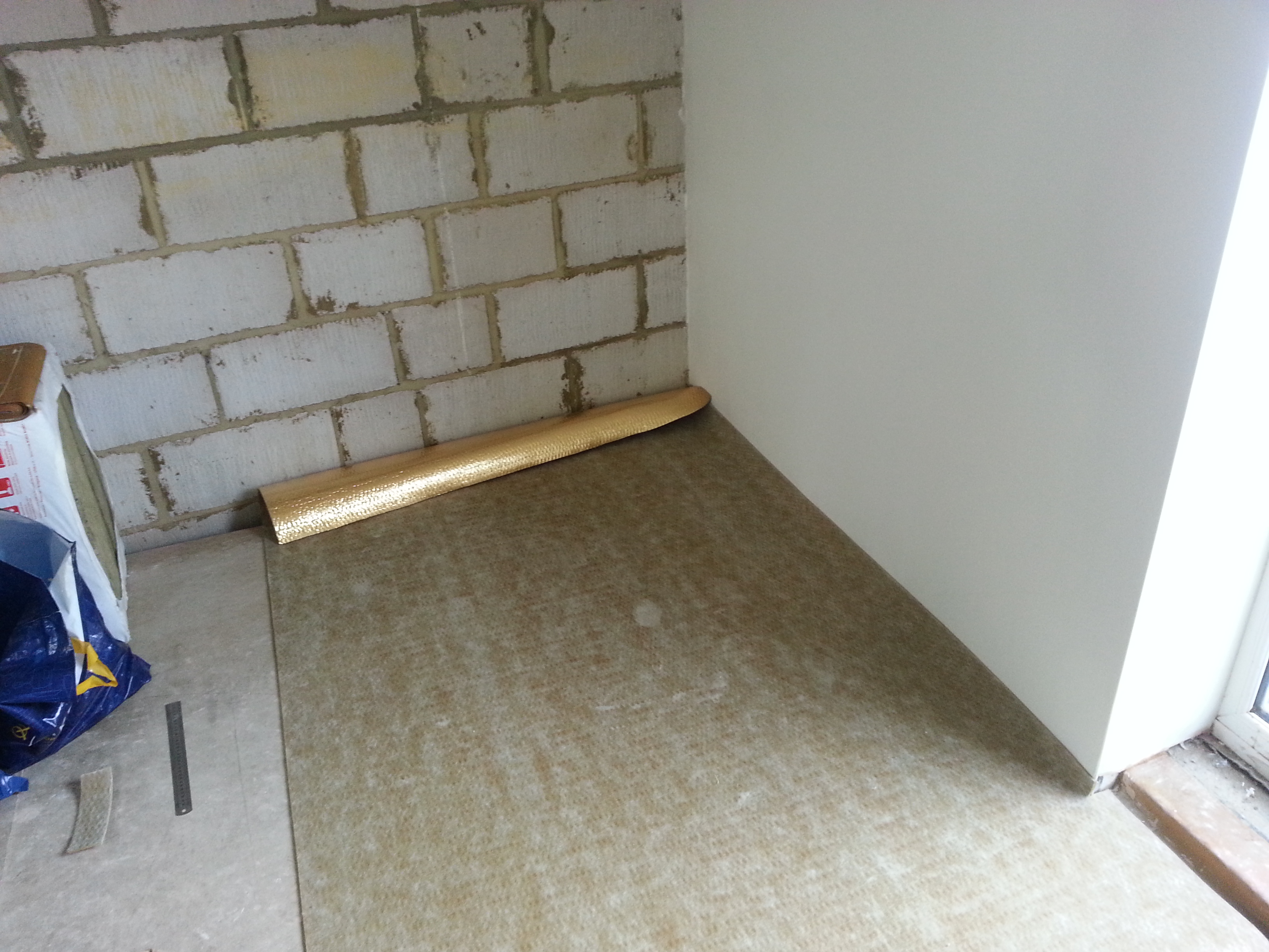
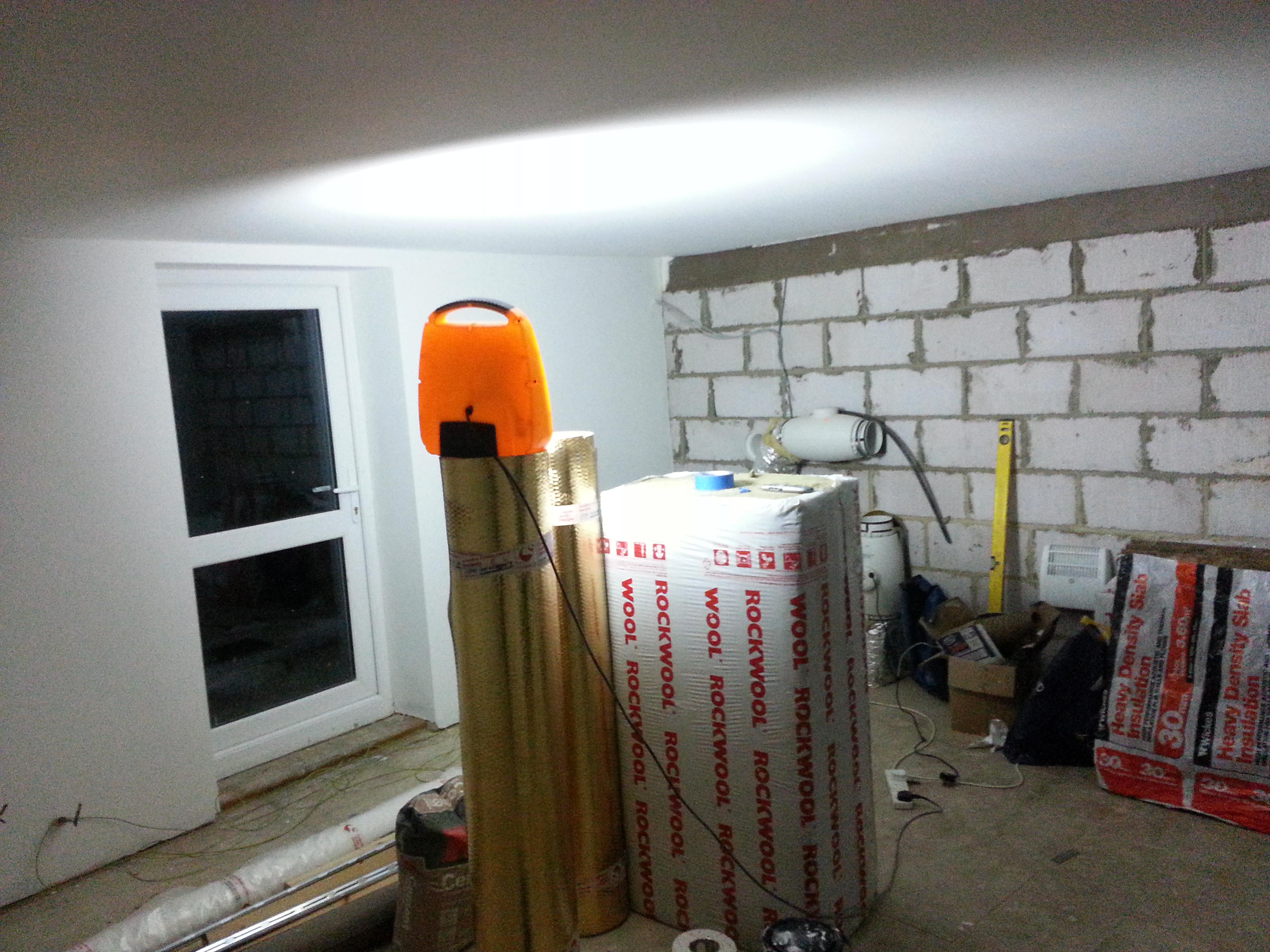
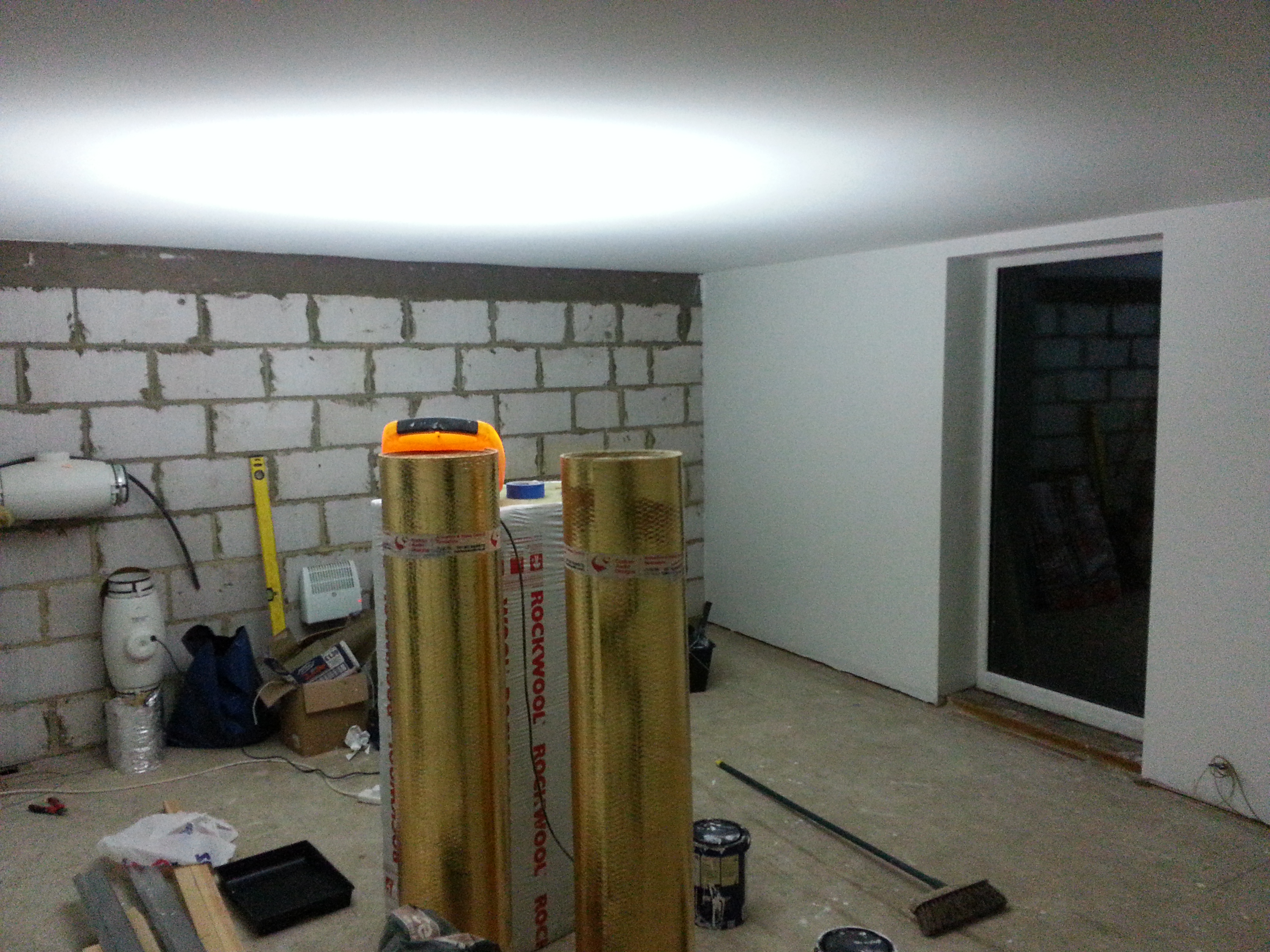
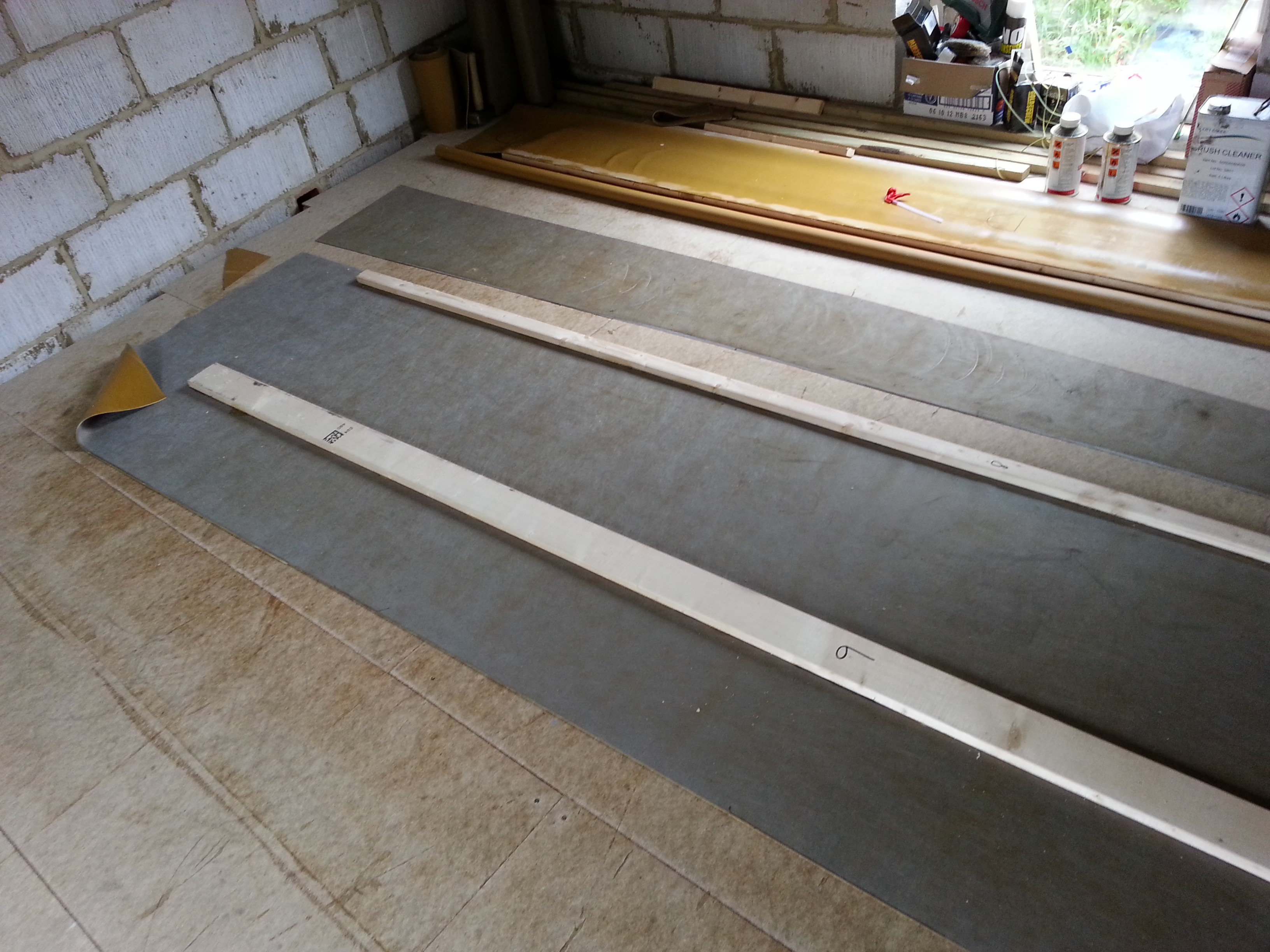
The following photos show how the Acoustic membrane was added to cover the dense fibreglass:
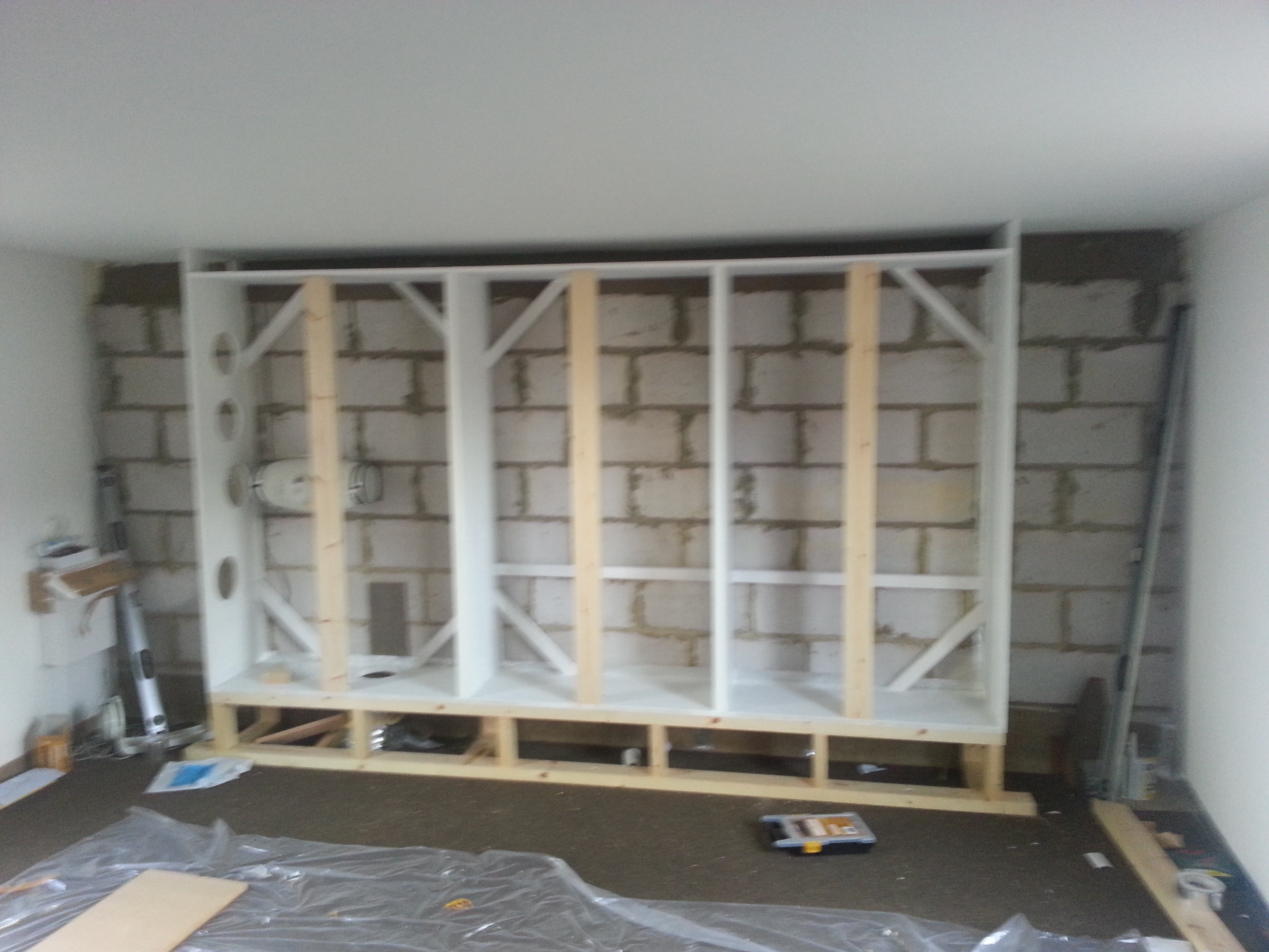
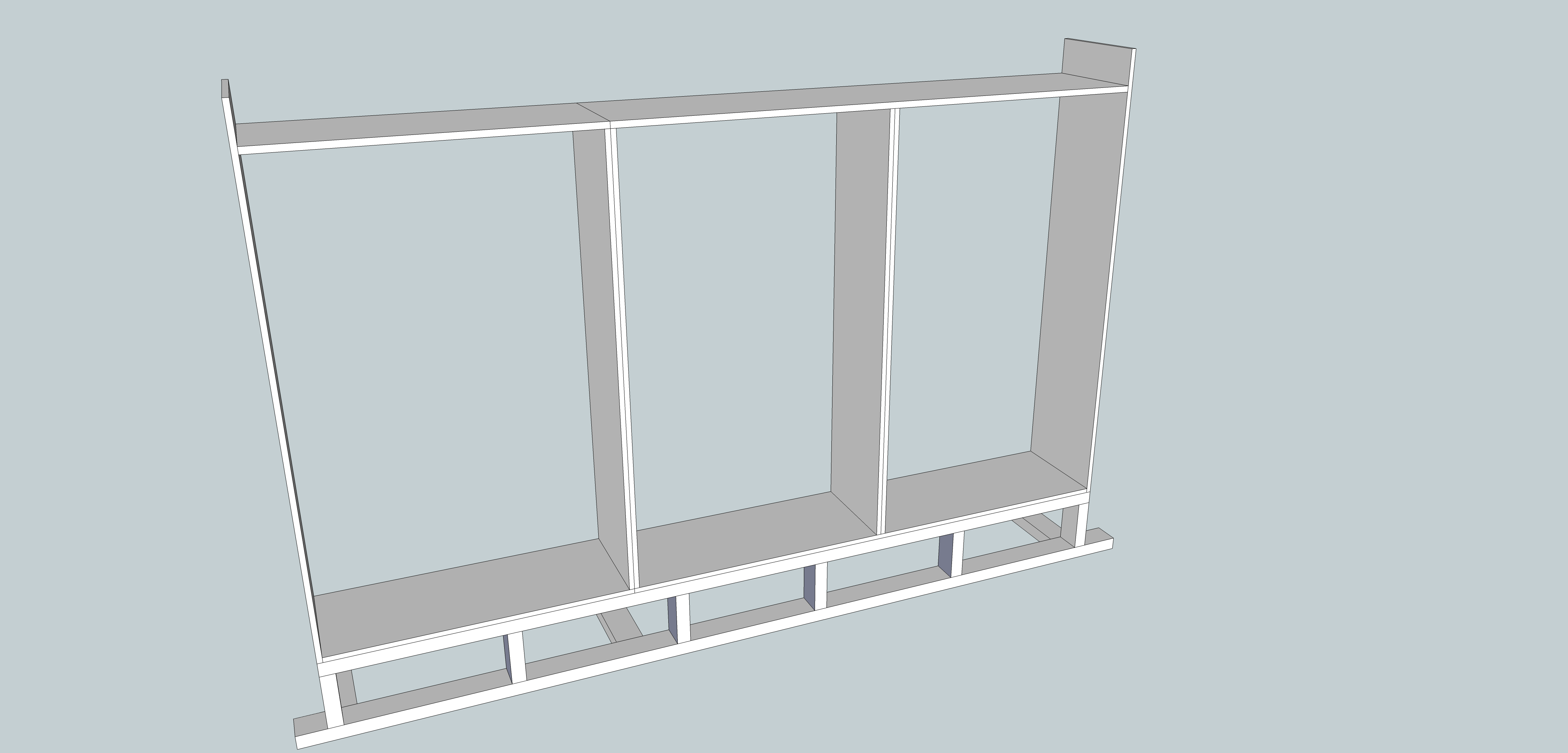
2013-05-20 17.46.36 2013-05-20 17.47.39 2013-05-25 14.36.37

Step 2 dig a hole, fill it with concrete

There are a whole bunch of possible ways when it comes to building a foundation.

Most of them start with digging a trench and filling it with concrete. If your building needs to comply with building regulations you’re best off agreeing the depth with them. They will take into account things like tree roots, types of soil, etc…

Although the studio did not need to be subject to building regs we were building an extension nearby that was. During one of their visits the regs officer was kind enough to give us some advice on the studio footings too.

The studio (at the time) was close to a bunch of Leylandii ‘trees’. For those who don’t know, Leylandii are bastards. They grow about 1 meter per year even in naff soil. These ones were massive. I have since got fed up with them and went at them with a saw, there’s now a nice fence there instead.

As a result of the trees, the Regulations Inspector suggested that we either go for deep foundations or consider going for a solid, steel reinforced concrete base.

I went for the Steel reinforced concrete base. Looking back, I have reservations about this which I will highlight below. Either way, the ‘method’ for this kind of base is as follows:

  1. We dug out the floor of the studio 200mm deeper than it would be when we were finished.
  2. We dug a trench around the outside just over half a metre deeper than the floor.
  3. We lay 100mm Celotex insulation board so it was to go beneath the floor.
  4. We covered the insulation and bottom of the trench with polythene membrane.
  5. We set up a steel mesh over the floor and going down into the trenches.
  6. We poured a hell of a lot of concrete into the hole until it was floor level. This step is shown in the picture below, apologies for the state of my phone camera.

2012-03-23 16.14.56

Costs

I’m not sure of the exact costs as we were also pouring a footing for some decking and a wall running up to the studio at the same time. But the total bill for the pouring phase came to just under £600 for the materials, £250 for the concrete pump and about the same again for labour. Total: ~ £1,100 for the pour.

Other items involved in the footings project were the insulation (about ~£40 for a 1.2m x 2.4m board) Digger Hire and skips for the excess dirt. In my case I’ve used much of the clay that we dug out of the footings for a garden landscaping project, this has saved a fortune in skips.

Total bill for the footings I would estimate at around £2000. You would need to allow for more for skips if you didn’t have a landscaping project in mind for all the soil you pull out.

Learning the hard way

Looking back, my choice of single pour solid base may be the start of my first mistake with the studio. I’m not sure if it was a certain thing then, but I have ended up with a wood beam floor in the studio. The wooden floor is supported by beams above the concrete base with an air gap between for ventilation.

This floor has the potential to resonate like a drum and will be a constant pain going forward.

I am where I am now and I can’t afford to change this. But I would recommend anyone else at this step stop to research and ask if there are alternatives to this configuration either available with the solid, single pour base or by going with a different kind of footing. I would be much happier if I could stand directly on the concrete base.

Step 1 Getting permission

No matter what country you are in there will be laws about what you can build and where.

Because I am building this in the UK on part of the same plot as an existing house I can use certain building rights called permitted development. Please note that this post is just my take on the rules and that if you are in doubt you should go to your local planning office and ask for their advice, my experience was that they were very helpful.

There are 2 ‘impediments’ to just building what you like in the UK: Planning permission and Building Regulations. Permitted development takes care of the planning permission aspect for quite a few extensions and outbuildings.

The government planning portal site provides some quite useful interactive graphics on what is allowed for extensions and outbuildings.

I doubt when this was debated in the house of commons the MPs were thinking about music studios, so the precise rules I am using generally refer to outbuildings like sheds and summerhouses.

More details for outbuildings are available here. However the basics are that, since I’ve not covered 50% of my garden even with the studio, I am free to build an outbuilding. Further I am not subject to building regulations providing it is either less than 15 sq m  or between 15 and 30 sq m and made out of ‘substantially non-combustible materials’. The only exception to this is the electrics which I will have to get signed off.

I figure that bricks and concrete count as non-combustible, and my studio works out to be a tad under 28 sq m.

As it happens, the chap doing most of the structural work for me is helping me keep it to regulations anyway. There have been a few times that this has lead to less than ideal acoustics (the damn wood beam floor is basically a big resonant cavity) , but I think keeping the building inspectors happy is probably better than to risk having to tear it down. TBH, the building inspectors have been very approachable even offering some advice on the studio when they had come round to review some work I’d done extending the house.

I should add that there was a 3rd even more important party that needed to approve of what I was doing – Kate, my very patient wife.

I also get the feeling that the bass drum should get a mention as an inanimate ambassador in all of this. By not fitting through the loft hatch, he resolutely took up storage in what is going to be the downstairs bathroom, thus re-prioritising the studio.

High five, Ambassador Bass drum.